🔍

Purchase the full subscription package now and enjoy a 40% discount, along with free updates for future editions.
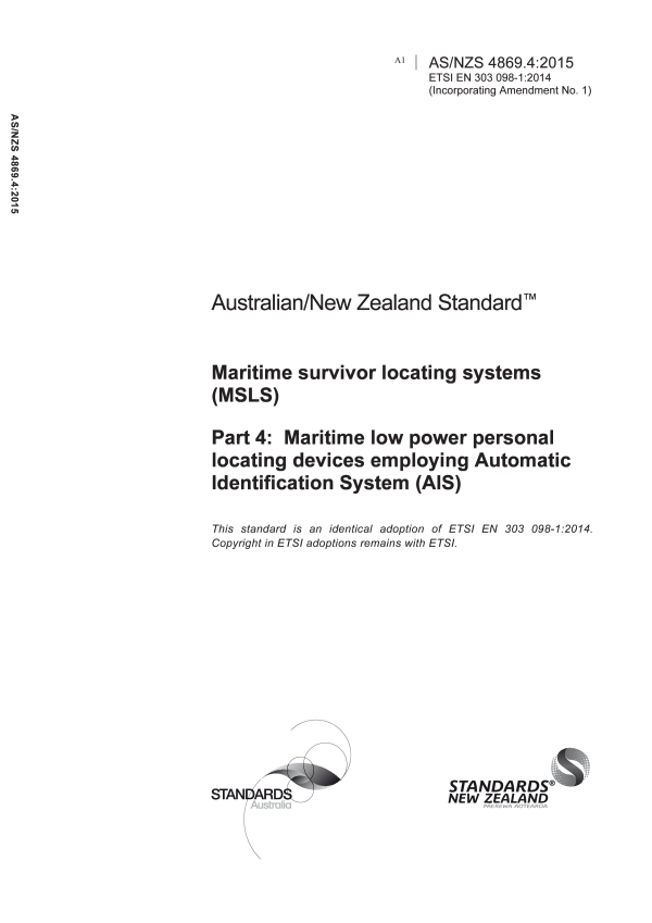
AS/NZS 4869.4:2015
$213.50
Maritime survivor locating systems (MSLS), Part 4: Maritime low power personal locating devices employing Automatic Identification System (AIS)
Adopts ETSI EN 303 098-1:2014 to specify essential requirements for maritime survivor locating devices (MSLD) that use automatic identification system (AIS) frequencies of 161.975 MHz and 162.025 MHz.
Table of contents
Header
About this publication
PREFACE
1 Scope
2 References
2.1 Normative references
2.2 Informative references
3 Definitions, symbols and abbreviations
3.1 Definitions
3.2 Symbols
3.3 Abbreviations
4 General requirements
4.1 Construction
4.1.1 Categories of equipment
4.2 Controls
4.3 Indicators
4.4 Identifier (user ID)
4.5 Labelling
4.5.1 Labelling Requirements
4.6 Instructions
4.7 Power source
4.7.1 Battery requirements
4.7.2 Battery capacity
4.7.3 Safety precautions
5 Technical requirements
5.1 General
5.2 AIS transmission characteristics
5.2.1 AIS messages
5.2.1.1 Active mode
5.2.1.2 Test mode
5.2.2 Synchronization
5.2.2.1 Active mode
5.2.2.2 Test mode
5.2.3 GNSS position source
5.2.3.1 UTC
5.2.3.2 UTC parameters storage
5.2.4 Required settings
5.2.5 Minimum transmitter performance characteristics
5.2.6 VHF Data Link (VDL) Access
5.2.6.1 Active mode
5.2.6.2 Test mode
6 General conditions of measurement
6.1 Conformity testing
6.2 Test Frequencies
6.3 Identifier (user ID)
6.4 Artificial Antenna
6.5 Test signals
6.5.1 Standard test signal number 1
6.5.2 Standard test signal number 2
6.5.3 Standard test signal number 3
6.5.4 Reference timing signal
6.6 Measurement uncertainty and interpretation of the measured results
6.6.1 Measurement uncertainty
6.6.2 Interpretation of the measurement results
6.7 Test conditions power sources and ambient temperatures
6.7.1 Normal and extreme test conditions
6.7.2 Test power source
6.8 Normal test conditions
6.8.1 Normal temperature and humidity
6.8.2 Normal test voltage
6.9 Extreme test conditions
6.9.1 Extreme temperatures
6.9.1.1 Procedure for tests at extreme temperatures
6.9.2 Extreme test voltages
6.9.2.1 Upper extreme test voltage
6.9.2.2 Lower extreme test voltage
7 Environmental tests
7.1 Introduction
7.2 Procedure
7.3 Performance check
7.4 Drop test
7.4.1 Definition
7.4.2 Test conditions
7.4.3 Method of measurement
7.4.4 Requirements
7.5 Temperature tests
7.5.1 Definition
7.5.2 Dry heat test
7.5.2.1 Method of measurement
7.5.2.2 Requirements
7.5.3 Damp heat test
7.5.3.1 Method of measurement
7.5.3.2 Requirements
7.5.4 Low temperature test
7.5.4.1 Method of measurement
7.5.4.2 Requirements
7.5.5 Low temperature battery endurance test
7.5.5.1 Method of measurement
7.5.5.2 Requirements
7.6 Vibration test
7.6.1 Definition
7.6.2 Method of measurement
7.6.3 Requirement
7.7 Corrosion test
7.7.1 Definition
7.7.2 Method of measurement
7.7.3 Requirements
7.8 Thermal shock test
7.8.1 Definition
7.8.2 Method of measurement
7.8.3 Requirements
7.9 Buoyancy test
7.9.1 Definition
7.9.2 Method of measurement
7.9.3 Requirements
7.10 Compass safe distance test
7.10.1 Definition
7.10.2 Method of measurement
7.10.3 Requirements
7.11 Solar radiation test
7.11.1 Definition
7.11.2 Method of measurement
7.11.3 Requirements
7.12 Oil resistance test
7.12.1 Definition
7.12.2 Method of measurement
7.12.3 Requirements
7.13 Protection of the transmitter
7.13.1 Definition
7.13.2 Method of measurement
7.13.3 Requirement
8 Tests on the AIS transmitter
8.1 Frequency error
8.1.1 Definition
8.1.2 Method of measurement
8.1.3 Limit
8.2 Conducted Power
8.2.1 Definition
8.2.2 Method of measurement under normal test conditions
8.2.3 Limit
8.3 Maximum Effective Radiated Power (ERP)
8.3.1 Definition
8.3.2 Method of measurement
8.3.3 Limits
8.4 Transmitter spectrum mask
8.4.1 Definition
8.4.2 Method of measurement
8.4.3 Limit
8.5 Transmitter transient behaviour (output power)
8.5.1 Definition
8.5.2 Method of measurement
8.5.3 Limit
8.6 Transmitter Transient Behaviour (frequency deviation)
8.6.1 Definition
8.6.2 Method of measurement
8.6.3 Limit
8.7 Synchronization accuracy
8.7.1 Definition
8.7.2 Method of measurement
8.7.3 Limit
8.8 Spurious emissions
8.8.1 Definition
8.8.2 Method of measurement
8.8.3 Limit
9 VDL Link layer tests
9.1 Active mode tests
9.1.1 Method of measurement
9.1.2 Initialization period – Required results
9.1.3 Message content of Message 1 – Required results
9.1.4 Message content of Message 14 – Required results
9.1.5 Transmission schedule for Message 1 – Required results
9.1.6 Communication state of Message 1 – Required results
9.1.7 Transmission schedule of Message 14 – Required results
9.1.8 Transmission with lost GNSS – Required results
9.2 Test mode tests with GNSS data available
9.2.1 Method of measurement
9.2.2 Required results
9.3 Test mode tests without GNSS data available
9.3.1 Method of measurement
9.3.2 Required results
Annex A
A.1 Test sites and general arrangements for measurements involving the use of radiated fields
A.1.1 Anechoic chamber
A.1.2 Anechoic chamber with a ground plane
A.1.3 OATS
A.1.4 Test antenna
A.1.5 Substitution antenna
A.1.6 Measuring antenna
A.2 Guidance on the use of radiation test sites
A.2.1 Verification of the test site
A.2.2 Preparation of the EUT
A.2.3 Power supplies to the EUT
A.2.4 Volume control setting for analogue speech tests
A.2.5 Range length
A.2.6 Site preparation
A.3 Coupling of signals
A.3.1 General
A.3.2 Data signals
A.4 Standard position
A.4.1 Artificial human support
A.4.2 Float-free support
Annex B
B.1 Active mode
B.2 Test mode
B.3 Default message field values
Annex C
Amendment Control Sheet
AS/NZS 4869.4:2015
Amendment No. 1 (2016)
Correction
Cited references in this standard
Content history
[Current]
DR AS/NZS 4869.4:2015
ETSI EN 303 098-1:2014
Please select a variation to view its description.
| Published | 23/12/2015 |
|---|---|
| Pages | 44 |
Please select a variation to view its pdf.
